As you may know from our previous posts – and specially if you were there – Insomni’hack 2011 is now over. As every year we had a lot of fun (and work) creating and developing the challenges and then looking at the teams (mentally) sweating to solve them while we were quietly drinking beer.
Despite the hacking challenges being the important part of the event (with beer drinking, of course) this topic has already been covered on SCRT’s website as well as on various participant’s blogs through solution write-ups and comments and is not our main topic here.
Indeed, like every year, we also try to design a few “side-challenges” aimed at amusing visitors and people having a break from the actual contest. These challenges do not provide any points (but can provide free beer) but allow us to explore and present a few other “hack-tivities” that cannot be easily incorporated in the main contest.
By doing these, we have over the years organised lock picking workshops, social engineering challenges and other alike events. This year however we wanted to add a more hardware related challenge. Something that would be fun for us to design and build and that could then be fun for visitors (or any other participant) to solve. That’s how the “Magic Box” project is born! As the project’s codename does not suggest, the original idea was to build a box stuffed with traps that the challengers would have to open.
Before going any further, we have to make very clear that none of the people that have been building this project (actually two SCRT engineers) is an electronics engineer. This will explain (and we hope) excuse some of our choices as well as some implementation details that would certainly cause a heart attack to any “real” electronics guy. This being said, the idea behind this post is to present this “box” and explain how it was built. Extracted from its context it is certainly not the most useful project to reproduce but it may actually give you any ideas for your projects.
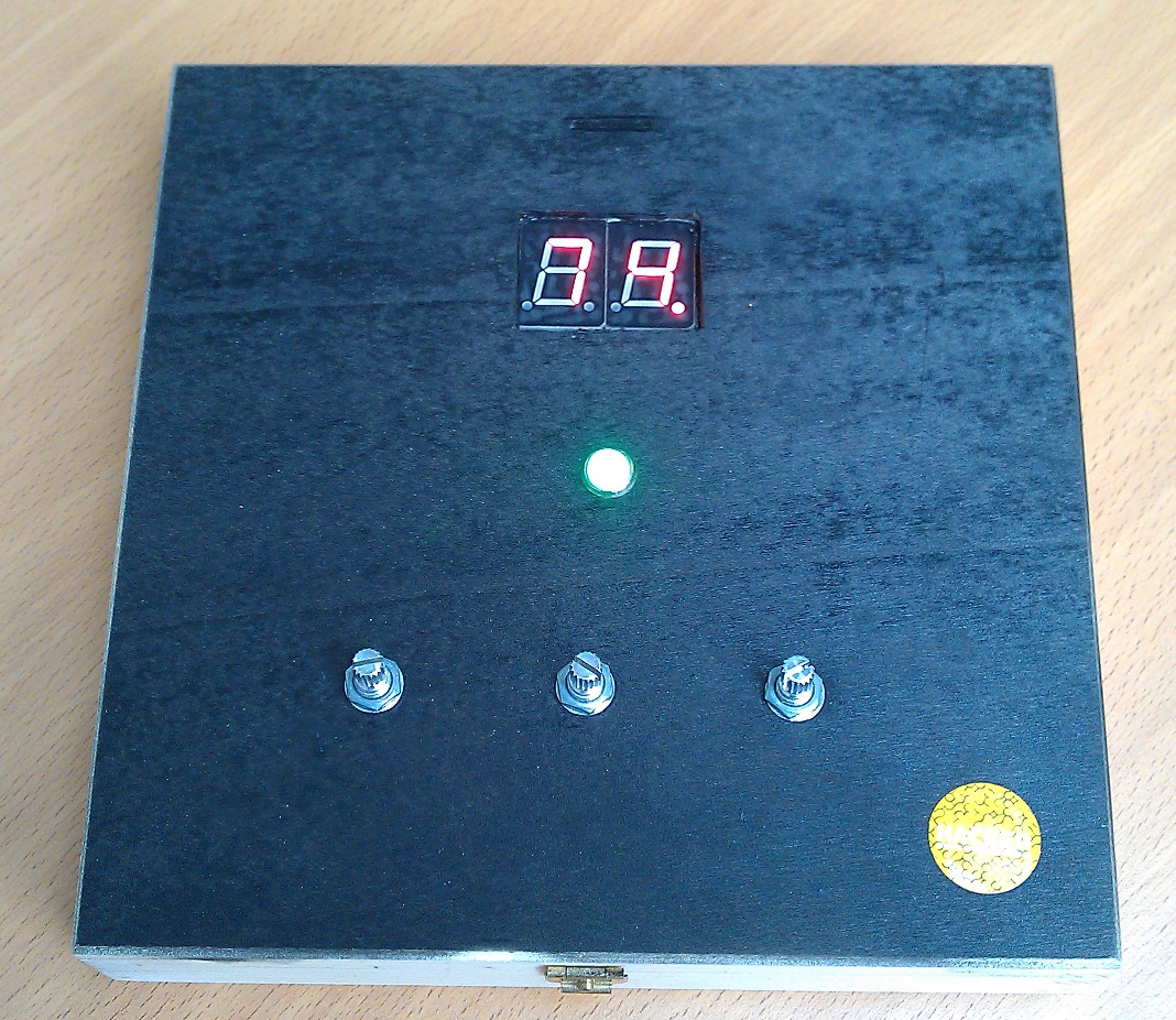
So let’s start from the beginning and present the box itself as is was presented to the challengers. It’s a wooden box having on it’s cover a two-digit display a LED and three potentiometers. The display was continuously counting down seconds, starting from 90 and each countdown step was underlined by a “beep”. Based on this, the challengers were given three attempts to open the box (by non-destructive means) without firing the alarm… simple, no?
So, before you ask, YES it was meant to look like some “Hollywood” inspired action movie bomb. And despite Bruce Willis did not show up to deactivate it, one participant succeeded!
Let’s now go deeper into the details and show what the participants could not see (unless they suceeded opening it) : the inside of the box !
At that point you certainly have already noticed the Arduino board. Yes, this project is based on Arduino! Why? Because it is simple, fun to work with and well documented! It would certainly have been interesting and cleaner, after the development phase, to port the project on a “naked” AVR microcontroller but we did not have time to do so. Maybe for Insomni’hack 2011.
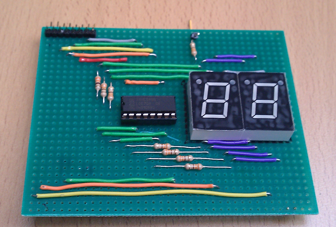
So, how does it work? First of all, the Arduino is used to drive the display board fixed to the box cover.
This board uses a 74HC595 shift register to drive two 7-segment elements. It also has a buzzer used to do the countdown “beeps” and the alarm sound. In order to spare one shift register, the display is multiplexed between the two elements. The whole process (countdown and display multiplexing) is implemented using one of the ATMEGA328 (the AVR microcontroller used in Arduino Uno boards) 8-bit timers : Timer 2. In more details, the timer is clocked it a prescaler of CPU_FREQ/256 which causes it to overflow approximately 244 times in one second. At each overflow the display is refreshed (by displaying the proper value on one of the two 7-segment elements thus causing each element to be powered on and off 122 times per second) and every 244 overflows the timer value is decreased. Note that all this process is driven by the timer and timer interrupts thus being completely independent from the main code.
[sourcecode language=”c”]
TCCR2A = 0; // Timer 2, normal mode (no PWM, no OC0A)
TCCR2B = 1 << CS22 | 1 << CS21 | 0 << CS20; //Timer2 Prescaler CPU_FREQ/256
TIMSK2 = 1 << TOIE2; //Timer2 Overflow Interrupt Enable
[/sourcecode]
[sourcecode language=”c”]
//Timer2 overflow interrupt vector handler
ISR(TIMER2_OVF_vect) {
overflows++;
if (overflows == CST_OVFLSEC) {
if (onDisplayValue > 0) {
onDisplayValue–;
if (onDisplayValue < 6)
do_bip(TONE_HIGH);
else
do_bip(TONE_LOW);
}
else {
expired = true;
}
overflows = 0;
}
do_refreshDisplay();
}
[/sourcecode]
This board is then fixed to ther box cover using a properly shaped piece of foam (recycled from some hardware delivery packaging) and … double-sided adhesive tape.
Aside from that board, the box cover was populated with the three potentiometers and the RGB LED all wired together. What for? That’s the real question! Indeed, These pots were used as (logical) unlocking mechanism. Here are the details.
A constantly monitored (by the Arduino) contact fires the alarm if the box is open … except if the proper unlocking code was previously set. This code was however not given in the form of a conventional numbered code but instead as a color! By turning the pots (which unsurprisingly control the R, G and B channels of the RGB LED) the participant changes the color of the LED. The state of these pots is monitored by the Arduino and if set to the proper values (with, of course some tolerance) allow the opening of the box.
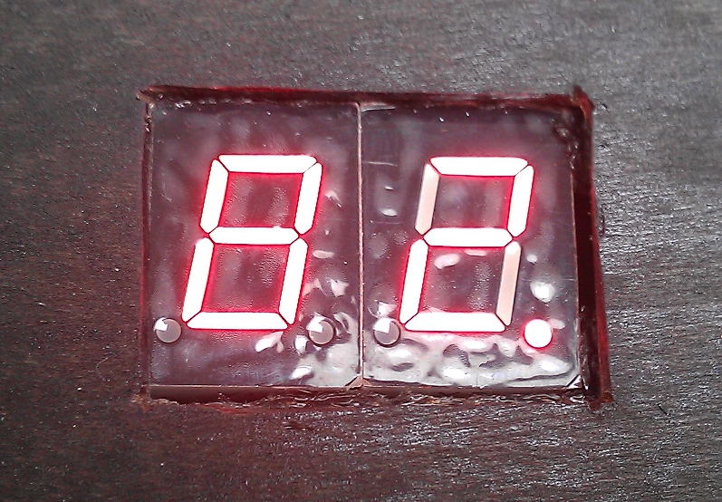
At this point, you may ask how can people know that the chosen color is the right one? First of all, a color indication was given to the participant in order to narrow his search (after all, 90 seconds is not much time). Then when the correct color was reached a visual indication was given: the decimal dot on the rightmost 7-segment display shuts off. This indication was not given to participants they thus had to observe it by themselves.
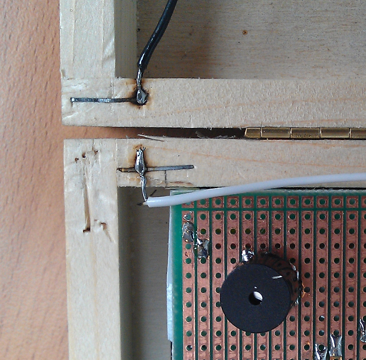
By now, you should have a good idea of how the box should be opened. However, having no indication about it’s details the participants spent a lot of time trying to figure out how to open it. But this would still be too simple if they could take the box and observe it in details (even closed). To prevent this we decided to make it a little bit more complicated by preventing the box from being messed with. The idea was simple: if the box is lifted from the table the alarm screams. This was pretty effective as it was one of the first participants’ reflexes. Fortunately they were given three attempts in order to learn from their mistakes.
From an implementation point of view, this was done by embedding a photocell under the box and monitoring it (through a voltage divider schema) from the Arduino. This way if the box was lifted the increased luminosity was detected by the Arduino and used to fire the alarm. This also provided an additional (bonus) trap as the photocell is sensitive enough to detect light coming from above, even when the box is on the table. Consequently it tends to fire the alarm if the box is open too wide, even if the proper unlock code is set 🙂
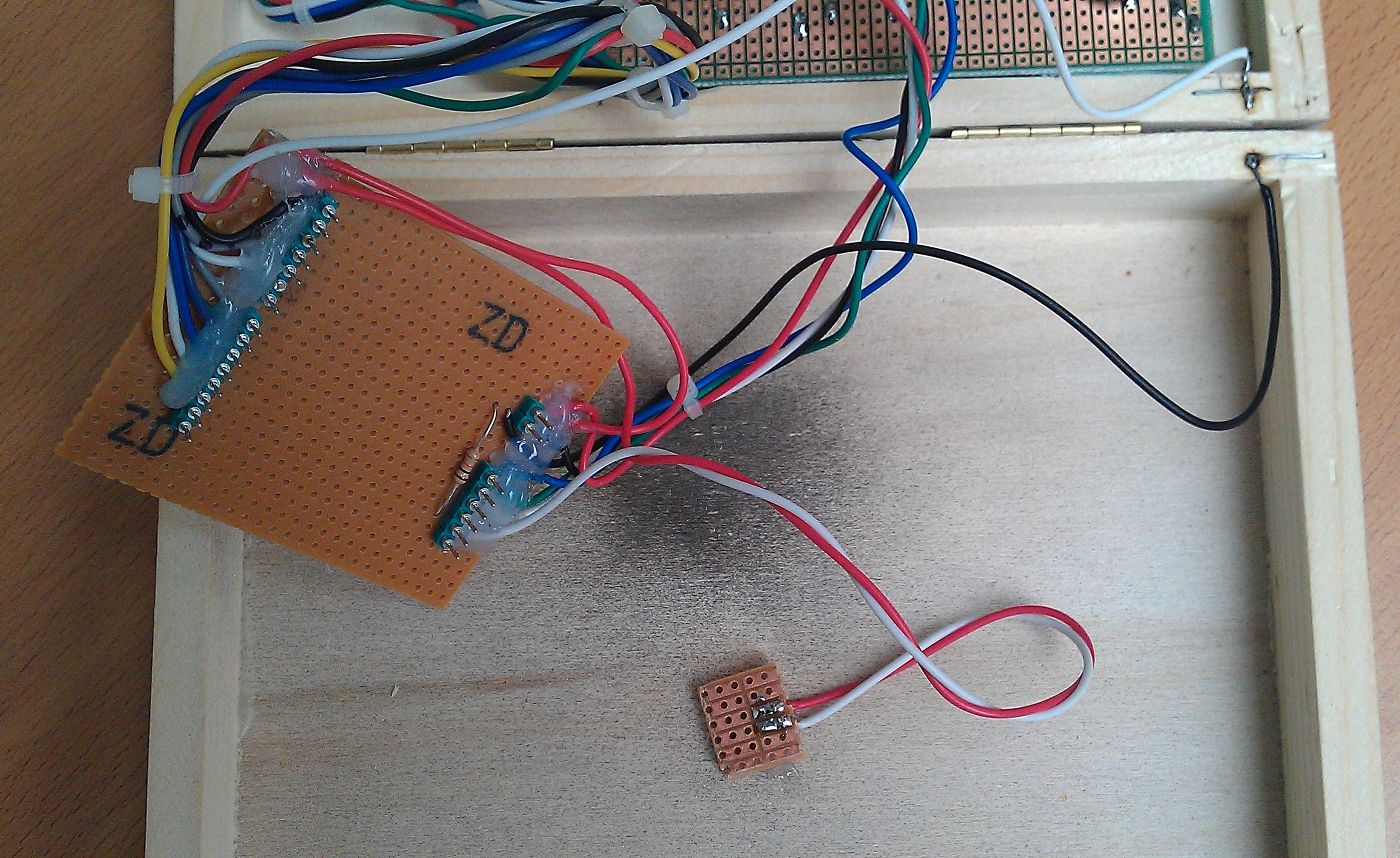
From an implementation point of view, all the fix elements were glued or taped to the box and connections were made to the Arduino. But as we wanted to retain the possibility to easily remove the Arduino itself, all the connection have been soldered to some hand-made “shield” (I apologize to the whole Arduino community for using the word “shield” for such a piece of crappy soldering on a strip-board…) that could the be plugged into the Arduino.
Finally, having described all the major internals of the box (and having omitted all the details that are too dirty to be posted), just remains to show the result. The two videos below show how it could go wrong and how the box should be opened.
In the end one participant could manage to successfully open it (we were less regarding to the number of re-attempts as our beer level was increasing) and has been given a free Arduino Uno board as a reward. As we had a lot of fun preparing this challenge it is most probable that Insomni’hack 2012 will have it’s “Magic Box” challenge again with new ideas and dirty soldering 🙂
[youtube=http://www.youtube.com/watch?v=dXjjjJ46ejA]
[youtube=http://www.youtube.com/watch?v=h_6BjGjsxeA]

